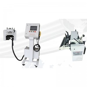
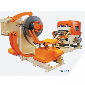
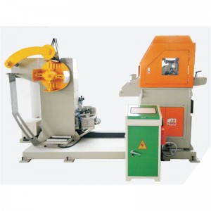
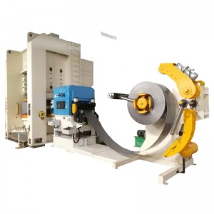
High Speed Roller Feeder


Characteristic
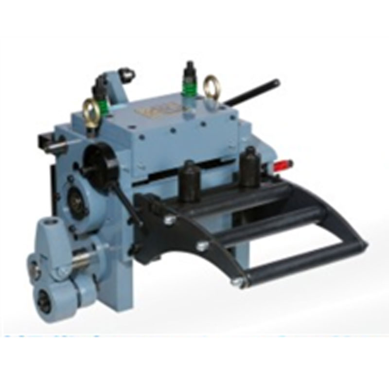
1. Leveling adjustment adopts electronic digital display meter reading;
2. High precision screw is driven by positive and negative two-way handwheel to control width adjustment;
3. The height of feeding line is adjusted by motor driven elevator;
4. A pair of hollow roller blocking device is used for material sheet;
5. Feeding roller and correction roller are made of high alloy bearing steel (hard chromium plating treatment);
6. Hydraulic pressing arm device;
7. The gear motor drives the feeding head device of the pressing wheel;
8. Hydraulic automatic feeding head device;
9. Hydraulic support head device;
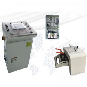
10. The feeding system is controlled by Mitsubishi PLC program;
11. The precision of feeding is controlled by Yaskawa servo motor and high precision planetary servo reducer;
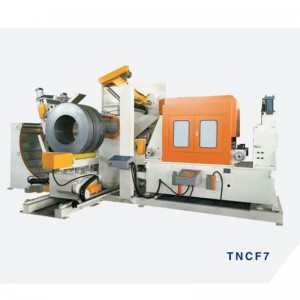
Equipment and adjustment of servo feeder
Local structure
1. High quality, brushless servo motor drive, useful to shorten the delivery distance, adjustment and testing time.
2. With high sensitivity decoder, feedback is accurate and feeder accuracy is improved.
3. When equipped with synchronous belt drive, it can eliminate gear gap, wear little, no noise, no lubrication, safe and environmental protection.
4. Mada hidden type, can prevent transfer and loading and unloading damage.
Equipment bur high speed
1. On one side of the punching machine table plate, drill and drill 4 holes according to the setting direction of the equipment board and fix the equipment board on it.
2. Lift the main part with a sling, align the key between the slide plate and the equipment board, and fix the main body on the equipment board with two matching screws.
3. When the height and horizontal direction of the feeder are inconsistent with the stamping of the die, the slide plate of NC feeder can be adjusted by about 100 mm. At this time, the two bolts on the slide plate can be loosened, and the bolts fixed on the equipment board can be adjusted. Then, the horizontal direction of the feeder can be changed. After reaching the appropriate position, the screws can be tightened.
4. Fix the mold to ensure that the direction of the mold and the roller is straight, and the equipment on the slide block of the punch has a good relaxation position. (Note: if there is a distance between the support plate and the lower die when stamping thin materials, it is necessary to install the material guiding equipment in order not to make the data tortuous, and the mold should be fixed straight with the roller, otherwise the data will be skewed, the feeder has resistance, and the feeding distance will be staggered.)
5. The electric control box and proximity switch should be installed at the appropriate position of the punching machine, and the normal operation of the electric control box and proximity switch should be tested.
Commissioning test example
1. Start the straightening machine or material rack to release the material slowly.
2. According to the width of the material, adjust the orientation of the two retaining wheels, which does not prevent the operation of the data.
3. Put the release handle on the stage, put the material between the upper and lower rollers, lower the release handle, loosen the fixed screw of the material thickness adjustment handle, adjust the handle up and down, so that the release bracket has a swing gap of about 5mm, and then lock the fixing screw of the handle. (Note: if there is no gap in the loosening bracket, the data will not be pressed tightly and slip, forming the feeder forbidden. When the thickness of the data changes, it is necessary to adjust from the beginning).
4. When the material is pressed, the material will not be pressed by the roller.
5. After setting the length of the feeder, depending on the actual situation, set the feeder speed accordingly. The setting method will be introduced in detail later.
6. After the relevant parameters of the feeder are set, the actual length of the feeder is not the same as the set value because of the approximate number. Therefore, the practical length of the feeder should be adjusted according to the feeder test, punch, stroke, stamping and adjustment in manual mode.
7. When the top of the guide pin in the mold enters into the guide pin hole, the screw rod can be adjusted to touch the bearing of the loosening support until the material loosening stops, and the screw nut is locked (for the pneumatic loosening feeder, the loosening point should be adjusted properly.
8. The adjustment of the starting point of the feeder is adjusted by the rotating cam of the press. The so-called starting signal of the feeder refers to the view point of the crankshaft of the punch to start the feeder. The recommended view point of the feeder is from 9:00 to 3:00.
9. After setting, the die should be tested by single punching first, and then the continuous production can be carried out after adjustment.